![]()
A Real-World Success Story in Structural Engineering
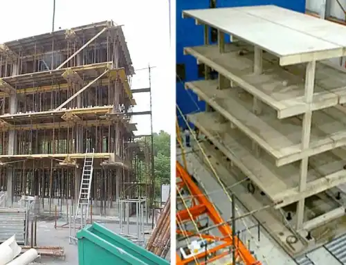
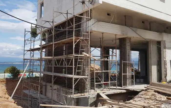
Upgrading existing buildings to meet modern seismic standards is one of the greatest challenges in structural engineering today. This case study highlights how a typical 1970s reinforced concrete hotel was transformed into a safe, resilient, and code-compliant structure—without compromising its functionality or architectural value. The project involved an 8-storey, 8,400 m² hotel, where seismic strengthening was successfully integrated into a full architectural renovation. (Figure 1).
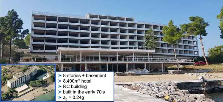
Figure 1. Front view of the building before the seismic retrofit and the architectural renovation
The building was analysed both before and after the strengthening interventions in accordance with Eurocode 8, Part 3, using the SeismoBuild software. SeismoBuild is an advanced finite element package dedicated to the linear and nonlinear assessment and strengthening of existing buildings. It employs the solution algorithms of SeismoStruct while automating the entire process—from intuitive structural modelling and linear (RSA) or nonlinear (pushover and dynamic) analysis, to code-based verification, CAD drawing export, and technical report generation. It is the ultimate tool for engineers who need to carry out code-compliant structural vulnerability assessment and seismic retrofit design of existing buildings, with speed, accuracy, and scientific rigor.
A comparison between SeismoBuild and SeismoStruct can be found here.
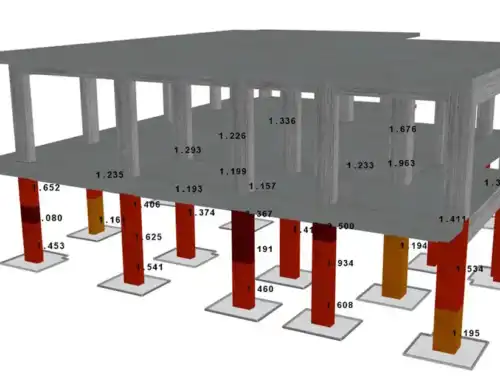
The buildings’ structural model without the infill walls is shown in Figure 2.


Figure 2. Structural model of the building (SeismoBuild screenshots)
The Challenge: State of the existing building
The hotel exhibited a series of structural deficiencies.
The most prominent feature of the building was its high irregularity in both plan and elevation. In plan view, one horizontal dimension was significantly larger than the other. Furthermore, the vertical load-bearing system consisted of numerous relatively small and weak columns, and no substantial structural walls were present, except for a lightly reinforced concrete core wall located at the perimeter of the elevator shaft, positioned on one side of the building (Figure 3).
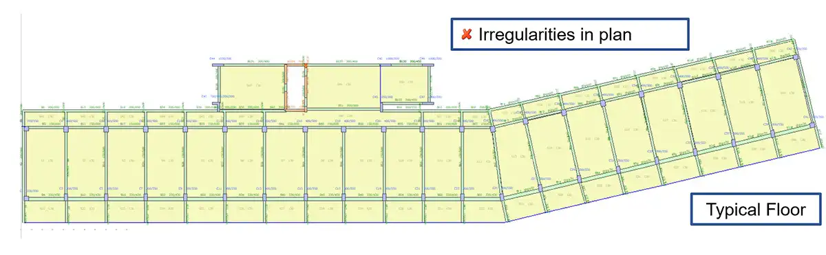
Figure 3. Plan view of the building’s typical floor. The columns are shown in blue and the concrete walls in orange (SeismoBuild screenshot)
In elevation, the deficiencies were even more critical. The building featured a typical soft ground storey with large open spaces and no infill walls. Additionally, directly above the soft storey, there was a short storey (h = 1.50 m) with reinforced concrete walls along its entire perimeter, originally intended to house mechanical installations. This configuration significantly accentuated vertical irregularities and amplified higher-mode effects (Figure 4). Furthermore, two columns (one at the front and one at the rear) terminated at the ground floor for architectural and operational reasons, allowing for large open spaces in the reception area. These columns were supported indirectly by two large beams at the level of the short storey. However, despite their large dimensions (150/50 cm), these beams were lightly reinforced and relatively weak (Figure 5).
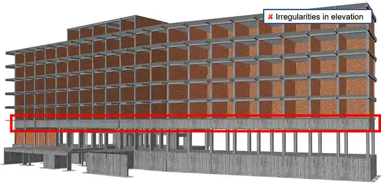
Figure 4. Front view of the building, where the stiff, short second floor is shown
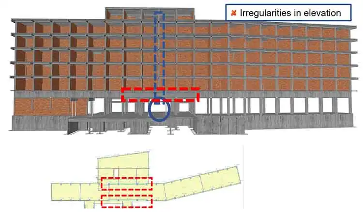
Figure 5. Front view of the building, where the indirect support of the columns on the large beams is shown
The column and beam dimensions were generally small, compared to modern standards, and the transverse reinforcement ratios were low with stirrups ∅8mm/250-300 and S220 steel grade. Combined with the absence of structural walls, this resulted in a highly flexible structure: the top displacement for the design earthquake was very close to the yield displacement (the design ground acceleration in the region is ag=0.24), as shown in Figure 6.


Figure 6. Typical pushover analyses (a) in the X-X direction and (b) in the Y-Y direction
Such large deformations might be acceptable in modern structures that are designed with high ductility. However, in older, low-ductility structures, this behaviour is unacceptable, indicating the necessity for structural upgrading. Moreover, a significant portion of the deformation was concentrated at the ground floor, which is a typical soft-storey behaviour. The interstorey drift at this level exceeded 1.0% under the design earthquake, signifying severe localized damage
The Solution: A Comprehensive Retrofit Strategy
As an initial strengthening measure, all vertical members were upgraded using reinforced concrete (RC) jacketing. A purely global strengthening strategy (e.g., adding only new RC walls or steel braces) was not considered sufficient, as the existing columns were deemed too weak to remain unstrengthened (Figure 7).


Figure 7. Strengthening of the columns with reinforced concrete jackets
In addition, new shear walls were introduced to increase lateral stiffness and eliminate plan irregularities. Along the short side of the building (Y-direction), two large shear walls, each 7.00 m wide, were constructed at both ends of the structure (Figure 8).


Figure 8. Strengthening of the new shear walls in the Y-direction
Along the long side (X-direction), however, the placement of large walls was not feasible, as this would interfere with the hotel’s operation by obstructing access to rooms. Instead, at six locations on the rear side, the jacketed columns were extended laterally to form wing walls in adjacent bays (Figure 9). Although these wing walls were smaller (2.0 m wide each), their combined contribution provided sufficient stiffness in the X-direction. All walls were extended along the full height of the building to avoid introducing vertical irregularities.


Figure 9. Strengthening of the new wing walls in the Y-direction
The existing lightly reinforced walls around the elevator shaft were strengthened using FRP (Fiber Reinforced Polymer) fabrics (Figure 10). RC jacketing was avoided in this case to prevent reducing the shaft dimensions, which were already too small for modern elevator standards.


Figure 10. FRP wrapping of the core walls in the perimeter of the elevator shaft
The two large beams of the ground floor that provided indirect support to the upper columns were strengthened with strong reinforced concrete jackets. Additionally, several other beams were strengthened using either four-sided RC jacketing or three-sided FRP wrapping (Figure 11).


Figure 11. Strengthening of the beams
The SeismoBuild model incorporating all strengthening interventions is shown in Figure 12.


Figure 12. Structural model of the strengthened building
Figure 13 presents typical capacity curves obtained from pushover analyses in both the X and Y directions. In addition to a substantial increase in lateral strength (by a factor of 2.5–3.0), there is a notable increase in stiffness and a reduction in target displacement. The target displacement now corresponds to approximately 50–60% of the maximum capacity. Combined with the enhanced ductility of the strengthened members, this indicates a significantly improved structural performance.
The building now meets modern seismic standards, offering safety, reliability, and long-term value. More importantly, the retrofit strategy has ensured significant structural upgrade without compromising the architectural layout and the operational functionality of the building.


Figure 13. Typical pushover curves in the X and the Y-direction
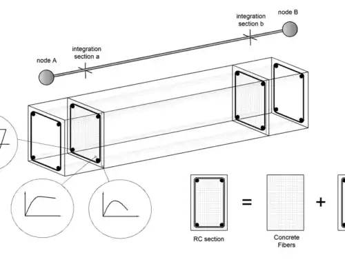
Typical cross-sections of the strengthened components are shown in Figure 14.


Figure 14. Typical cross sections from the design of the interventions
Final Remarks
The design of strengthening interventions presents significant challenges for engineers, both at the design stage and during construction. The careful identification of the technical, operational, social, and performance criteria involved is essential to achieving an optimal retrofit solution.
In practice, compromises are often unavoidable, requiring balanced trade-offs between competing objectives to deliver the best overall outcome. Specialized knowledge, practical experience, and sound engineering judgment are crucial in order to objectively evaluate the advantages and limitations of alternative solutions and to select the most appropriate strategy. In many cases, a combination of different strengthening methods is necessary to achieve optimal performance, ensuring a substantial improvement in structural capacity, stiffness, and ductility.
References
Alfakat S.A. (2026). Strengthening of an 8-storey hotel in Chalkida, Greece. Available at: https://www.alfakat.gr/en/project/seismic-retrofit-on-an-8-storey-hotel-in-chalkida/ (Accessed: April 13, 2026).
Antoniou, S. (2023). Seismic Retrofit of Existing Reinforced Concrete Buildings, 1st Edition. Print ISBN: 9781119987321, Online ISBN:9781119987352, DOI:10.1002/9781119987352. John Wiley & Sons Ltd.
CEN (2004). EN 1998-1:2004. Design of structures for earthquake resistance -Part 1: General rules, seismic actions and rules for buildings, Comité Européen de Normalisation, Brussels.
CEN (2005). EN 1998-3:2005. Eurocode 8: Design of structures for earthquake resistance – Part 3: Assessment and retrofitting of buildings, Comité Européen de Normalisation, Brussels.
SeismoBuild (2026). SeismoBuild – A computer program for the linear and nonlinear analysis of Reinforced Concrete and Steel Buildings.