![]()
Table of Contents
Application
Advantages and Disadvantages
Design Issues: Modelling Analysis and Checks
Application
Steel bracing offers similar advantages to new shear walls, increasing the strength, the stiffness and the ductility of the building. The braces are commonly constructed inside existing bays of the building and they contribute to the lateral resistance of the structure through the axial force developing in their inclined members. The diagonals are pinned to steel plates that are anchored at the corners of each concrete bay with epoxy resins, whereas at the ground level special footing configurations for each brace are provided.
Similarly to the case of new RC walls, the braces should be placed in symmetrical positions, so as to not introduce unwanted torsion in the building, and, if possible, reduce in-plane irregularities. Although the construction of steel braces considerably increases the lateral capacity of the building, it only increases its stiffness moderately. Consequently, it is not as effective as other methods in stiff concrete structures, such as wall or dual systems or masonry infilled frame.
In general, there are two different types of steel bracing systems, the concentric (Figure 1a) and the eccentric (Figure 1b) braces. Concentric bracing systems are the most widely used for retrofitting concrete frames. Bracing systems suitable for structural retrofit are those with X-braces along both diagonals of the braced bay, or diagonal braces, in which there is a single diagonal per bay of the frame. V or inverted V braces (‘chevron braces’ in the USA), in which the inclined braces are connected to the mid-span of the horizontal member (usually a beam) of the bay, are not so common, whereas K braces are not allowed due to the introduction of high inelastic demand at the columns. Finally, buckling-restrained bracing, in which global buckling is inhibited by appropriate systems, can also be introduced.

(a)

(b)
Figure 1: Typical (a) Concentric and (b) Eccentric Steel Braces in retrofit
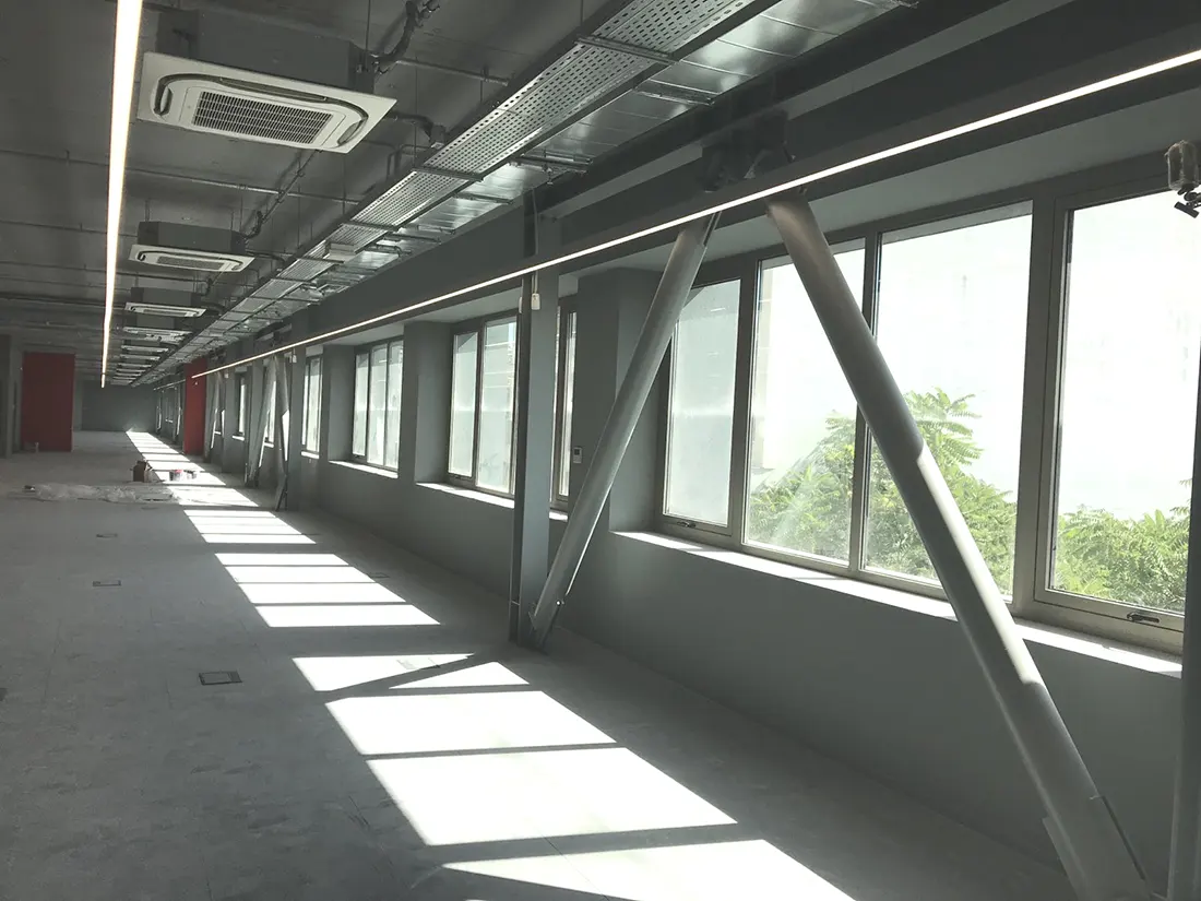
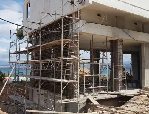
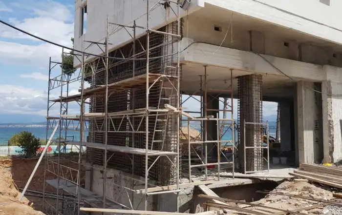
Figure 2: Concentric steel braces in retrofit ( photograph by courtesy of Christos Giannelos)
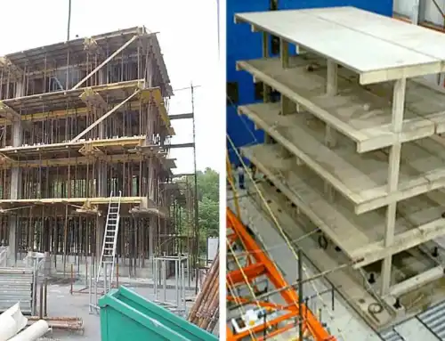
Sometimes the braces can be extended in more than one bays or floors of the building frame (Figure 3). Two V-braces, one inverted in one bay and one normal in the bay on top, can be combined to form a large X-brace between two storeys. Because the braces in the two storeys are effectively continuous, the shear forces from the diagonals on the intermediate beam cancel each other, and the shear demand on the beam is limited.
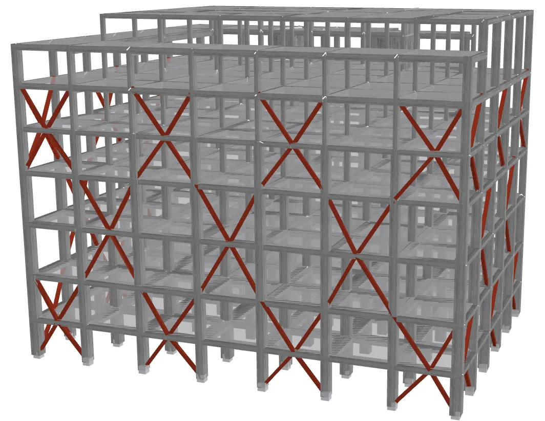
Figure 3: Two V-braces combined to form a larger X-brace in two storeys (SeismoStruct screenshot)
In a similar technique, steel external trusses (also named as exoskeletons) can also be constructed at the perimeter of the building (Figure 4). These trusses consist of strong steel composite frames with diagonal members, and are connected to the existing framing system through large steel connectors, by which way they are able to undertake and transfer to the ground the seismic loading that acts on the frame.

Figure 4: External steel trusses*
Advantages and Disadvantages
Steel bracing, by providing strength and stiffness, generally decrease the seismic demand on existing members, similarly to new RC shear walls (though usually to a lesser extent with respect to the latter). The level of strength and stiffness increase can be tuned relatively easily by the choice of the number and the size of the braces, and it is easy to avoid large irregularities in elevation. Bracing is an ideal solution for the strengthening of soft ground storeys, where the steel braces are applied only at the lower building level.
The added weight to the building is minimal, whereas braces possess the ability to accommodate for existing openings. Furthermore, it is a ‘cleaner’ construction method, because the braces are directly fitted to the concrete frame without the introduction of concrete and the creation of dust in the building. For larger buildings, steel bracing can be easily combined with dampers, in order to reduce the seismic demand.
The main disadvantage of the technique is that it is usually difficult to find locations and bays of the building for the placement of the braces, since their distribution on the plan view of the building should be as symmetrical and uniform as possible. Furthermore, steel braces are not efficient for stiff concrete structures with large shear walls, although this is the exception in older construction. Moreover, it is not always easy to achieve high quality welding on site, and the control of the interaction between new steel and existing concrete system is also difficult.
Design Issues: Modelling Analysis and Checks
Local buckling of the braces is the most important factor limiting the ductility and the energy dissipation of the system, since it generally precipitates fracture. Regardless of whether the braces under compression are considered or neglected in the analysis, their design should consider measures against buckling, and their slenderness should be limited (for example Eurocode 8 requires sections of class 1 or 2 for behaviour factors larger than 2.0).
The strength of the braces and the strength and deformations of the adjacent concrete members and beam-column joints are evaluated using the existing design guidelines. In linear analysis, a force-based approach is employed and the checks are mainly carried out in terms of forces. In nonlinear analysis, deformation-based criteria are employed for the braces, intended to check the energy dissipation of the system. In general, it is assumed that the bracing system has a dominant role in undertaking the lateral seismic loads; hence their designation as primary is essential.
References
- *All the pictures, which are in the article and are not referenced, are courtesy of Alfakat (www.alfakat.gr), an official partner of Seismosoft.
- Structural Assessment, Strengthening & Retrofitting carried out using SeismoSoft Earthquake Engineering Software.