

![]()
Table of Contents
Application
Foundation Systems of new Shear Walls
Advantages and Disadvantages
Design Issues: Modelling and Analysis
Application
This method consists of the construction of new shear walls with large dimensions at selected locations in the building perimeter and/or in the interior of the building. The walls can have a very beneficial effect on the seismic performance of existing buildings, providing simultaneously a considerable increase in the strength, stiffness and ductility. One very important advantage of the method is the significant decrease in the demand on existing lightly reinforced members of the building, due to the large dimensions and very large stiffness of the new members.
A typical cross-section of a new shear wall added to an existing building is very similar to shear walls of new buildings, with pseudo-columns with closely spaced stirrups at the two edges, and a lightly reinforced web that is expected to sustain damage in a strong seismic event. The only significant difference is the large number of dowels that are employed for the connection of the new and the existing members, and the safe transfer of the seismic inertia forces from the existing building to the ground, through the new walls.
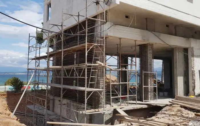
It is generally preferable that the wall encapsulates two columns of the existing building, to form strong and ductile jackets, which constitute the pseudo-columns at the edges of the new wall. The jackets can be constructed by cast-in-place concrete together with the wall web (employing formworks around the existing members, columns and beams) or separately using shotcrete. Ideally the new wall is sufficiently thick, so as to also encapsulate the existing beam that connects the two columns. Consequently, wall thicknesses of 35-40 cm are not uncommon (Figure 1).


Figure 1*: New shear walls in existing RC buildings
The lapping of the longitudinal rebars from one storey to the adjacent, and the placement of the stirrups is done in a similar fashion to the jackets’ reinforcement; that is by creating holes in the slabs and the beams. Larger holes are also needed for the casting of the concrete. In the typical case, due to the large width of the walls, more than one hole is needed.
Because of the very large stiffness of these new components with respect to the existing vertical members, particular attention should be paid so that the new walls do not unintentionally cause large stiffness irregularities. Hence, it is important that the new walls are added in a symmetric fashion on plan view, in order not to introduce significant torsional effects in the seismic behaviour. This means that at least two walls should be placed in each horizontal direction symmetrically with respect to the centre of mass of the floor (Figure 2). Failing to add walls in one of the two directions for architectural or economic reasons means that the building is strengthened only in one direction, and is left unstrengthened in the perpendicular one (Figure 3). Note however, that the construction of walls on the three sides is also acceptable, since it provides adequate translational and rotation stiffness to the building.
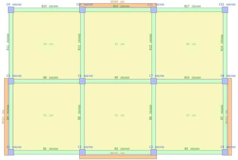
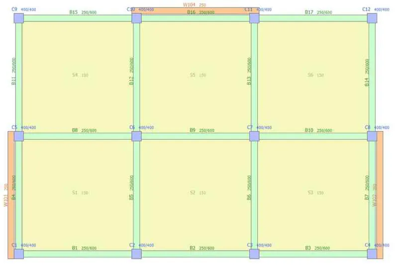
Figure 2: Acceptable placement of new shear walls on plan view
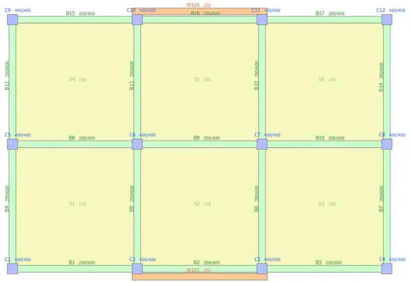
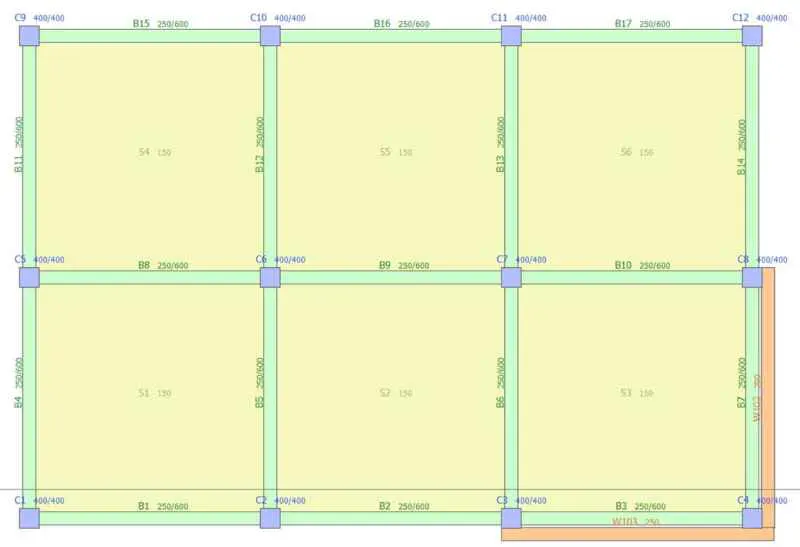
Figure 3: Unacceptable placement of new shear walls on plan view
Likewise, if the walls stop abruptly at some level along the height of the building (e.g. if they are constructed only at the ground level), this will lead to significant irregularities in elevation and strong, undesirable higher-mode effects, increasing the vulnerability of the floor right above the end of the walls. Therefore, in most of the cases the walls should be extended to the entire height of the building, although a gradual decrease in their width is acceptable (if not desirable).
There are three ways of strengthening a building with RC shear walls:
- The walls are added inside the building bays, usually surrounding the existing columns to form their pseudo-columns (Figure 4a).
- The walls are constructed right outside the perimeter of the building. A large number of strong dowels or connectors are required so that the new walls are adequately connected to the existing building. The main advantage of this variation is that the disturbance to the occupants is minimal (Figure 4b).
- The walls are added in the form of buttresses at the extremities of the external frames ( Figure 4c).
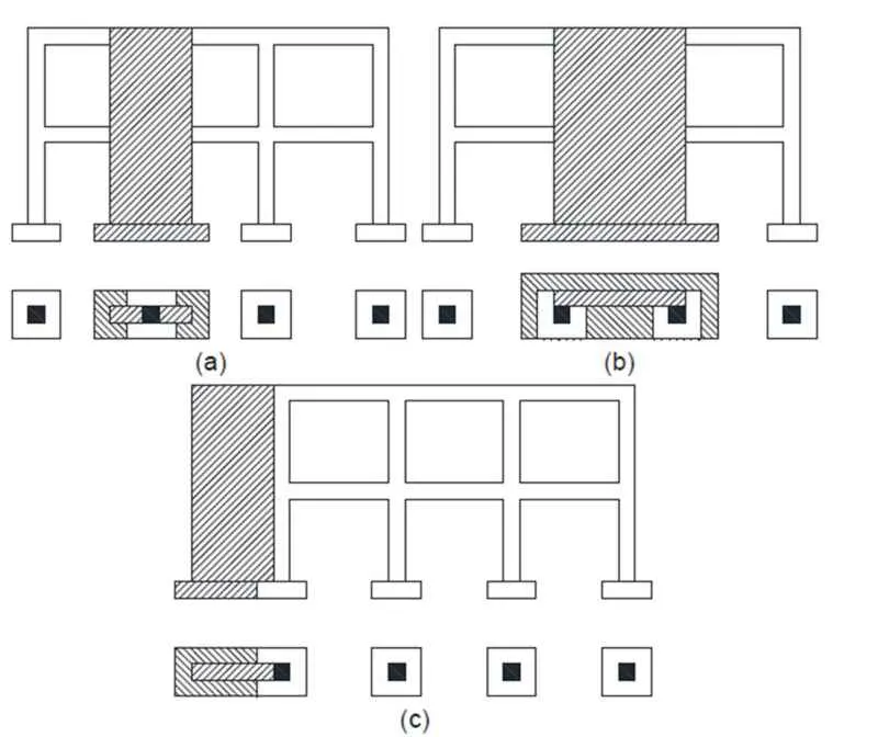
Figure 4: View and cross-section above the foundation of RC frames strengthened with new RC walls placed (a) internally, (b) external, or (c) as buttress [Tsionis et al. 2014]
The first option entails higher disturbance to the occupants and increased cost due to intensive secondary interventions, i.e. repairs damage. The two others minimize disturbance, but in turn require more space outside the building, which might not be available.
Although external buttresses have all the advantages of walls constructed close to the building and they minimize the disruption, this option is rarely employed. Apart from the obvious space requirements, which are fulfilled only by a small proportion of the building stock, they have questionable aesthetic quality and pose significant architectural problems and restrictions, creating large shaded areas that reduce internal lighting. Furthermore, the connection of the buttress to the building is an intricate issue. Although such buttresses are connected to the existing building at all levels, the connection areas are subjected to very large shear force levels, even under compression, and often the available space for the placement of dowels is not enough. Buttress stability is another major issue, since buttresses are not loaded vertically but for their own weight, which increases the possibility of uplifting of the foundation and reduces their effectiveness to resist lateral loads.
The most common problem with this method is that very often the existing openings do not allow for the symmetric placing of the walls in the perimeter of the building. In the general case, there are not many walls without openings in the entire building height, or walls where the openings can be cancelled without affecting the building from an architectural and operational perspective. For instance, it is not possible to add a wall in front of the entrance of a building, or a wall in a location that closes the door to a room or a balcony. Furthermore, due to the very large size of new walls with respect to the existing structural elements, this type of intervention is particularly invasive, hence a certain sensitivity to architectural aspects is required.
Usually, in practical applications a combination of internal and external (in the perimeter) walls is employed. Where the geometry of the building allows it, the new walls are added in the perimeter. If instead this is not possible (e.g. there is not enough space, the existing openings are preventing it, or there are party walls with the adjoining properties), internal walls are chosen instead.
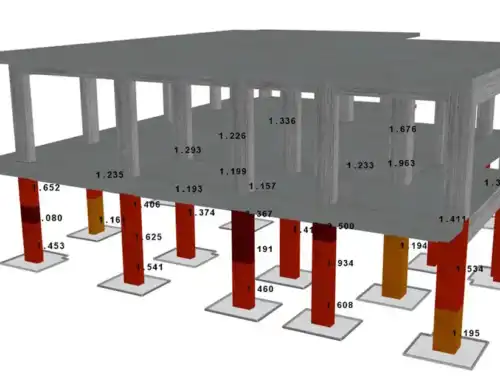
With the introduction of the new walls and because of their very large stiffness in the direction of their largest dimension (recall that the elastic moment of inertia is bh3/12), the new walls attract a large proportion of the seismic inertia forces, which can be as much as 70 or 80% of the total, if the walls are adequately large and symmetrically placed in the perimeter of the building. This means that the seismic demand on the existing vertical members drops significantly at a similar proportion, which enables them to withstand the applied forces even with the reduced existing reinforcement. Simultaneously, there is also a considerable reduction in the fundamental period, which can be up to 50%, resulting in a completely different dynamic behaviour. What is more, the new walls typically change the structural failure mechanism to a beam-sway one.
Consequently, new walls are often introduced without the strengthening of the other existing columns. This is of particular importance in buildings that are in operation for the duration of the works, because it considerably reduces the locations of intervention and the corresponding costs for non-structural damage and repair (e.g. tiles, floors, windows).
On the negative side however, these increased forces applied on the new walls leads to extreme requirements at the foundation level that often cannot be fulfilled with normal footing dimensions. Finally, increased chord rotation and shear demands are imposed on the beams that are directly connected to the wall and lie within its plane. The beams are usually unable to resist such demands, if they are not retrofitted too.
Foundation Systems of new Shear Walls
Considering that a very large proportion of the base shear is undertaken by just a few vertical members of the building, a significant issue that is to be considered when adding large shear walls is how the transfer of these forces and the corresponding overturning moments to the ground is achieved. This generally requires significant interventions on the foundation level for each wall.
A small footing of these large walls will result in rocking rotations and uplifting, overturning moments below the value calculated assuming fixed support conditions, and finally considerable increase in the lateral floor displacements and reduced effectiveness of the proposed strengthening scheme. Therefore, it is important to reduce the rocking and uplift of the wall footing, which can be achieved by the following means:
- By increasing the vertical load acting on the footing. This can be done by increasing the size and the weight of the footing, and by enclosing the footings of the adjacent columns, in order to activate a larger percentage of the gravity loads of the building.
- By connecting the new footing to the neighbouring footing with large, strong and stiff connecting beams.
- In cases of very large overturning moments, it is beneficial to use micro-piles, instead of shallow foundation elements.
All of these methods are costly and more importantly very disruptive to the building’s operation, since they require serious interventions on the ground level and the uncovering of the existing foundation system in a large area. To some extent these disruptions can be moderated with the introduction of eccentric footings, for instance in the walls at the perimeter. Nevertheless, the required size of the foundation is such that it should always be considered, when choosing the method of adding new shear walls in existing buildings.
Advantages and Disadvantages
New shear walls improve the global response of the building in terms of strength, stiffness, deformation capacity and ductility. They significantly reduce the storey drifts, they may prevent storey mechanisms and, depending on the layout of the existing building and the location of the new components, they may also reduce irregularity, both height-wise and in plan. Because of their very large stiffness with respect to the existing vertical members, they may lead to increased building strength that can be as high as 200-300% of the initial strength. Consequently, the lateral seismic loads are mainly resisted by these new components, which are appropriately designed (reinforcement and detailing) to withstand them.
This in turn results in a very large reduction of the seismic force and drift demands to the other building members that can be as high as 70-80%. These members are expected to play a secondary role, mainly carrying gravity loads, and the need for strengthening is eliminated in all or most of them. This is of particular importance in buildings that are in operation during the duration of the works, since it considerably reduces the locations of intervention, the disturbance to the buildings’ operation, and the corresponding costs for non-structural damage and repair (e.g. tiles, floors, openings). In addition, the non-structural building components are expected to sustain reduced damage during a large seismic event, because of the reduced deformations.
On the negative side, very often there are limited locations, where the walls can be added. Usually, the walls should be constructed throughout the entire height of the building, so as to not introduce significant irregularities in elevation, and should be placed in a symmetric fashion on plan view, otherwise significant torsional effects are induced. As a result, it is often difficult or impossible to find appropriate locations for their placement, especially in buildings that do not have a typical floor plan at the different levels.
Another problem of new shear walls is that they require the construction of very large (often gigantic) footings at the ground level, in order to avoid rocking, which is undesirable. This, apart from the obvious increased cost, leads to very disruptive works at the ground level, where the building entrances are.
Design Issues: Modelling and Analysis
New shear walls are typically designed and detailed as in new structures, taking into account all the corresponding capacity design principles. At the two edges of the cross section, there are well confined pseudo-columns with closely spaced stirrups, whereas the web remains lightly reinforced and is expected to sustain damage and to absorb energy.
The walls are over-reinforced against shear (i.e. taking into account the increased demand), in order to make sure that the wall first yields in flexure. Furthermore, plastic hinges and yielding should only be allowed at the base with the over-design (increased demand) in flexure above the plastic hinge. Plastic-hinges at higher levels should be avoided, in order to preclude the generation of unwanted higher-mode effects that could be caused by inelastic response. Steel connectors and dowels should also be calculated using capacity design provisions, thus preventing any failure of the connectors that could again cause higher-mode effects.
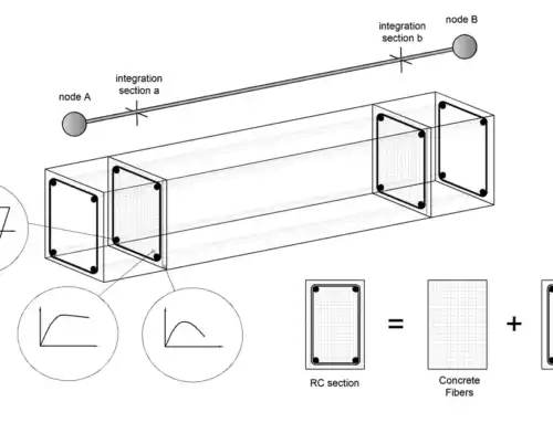
In linear analysis the new walls can be modelled as rectangular or triangular shell elements. On the contrary in nonlinear static (pushover) or dynamic analysis, the walls are typically modelled as one-dimensional nonlinear elements. The offset between the axis of the walls and the beam edges, which can be as high as 2.00 m or more is typically covered with rigid links (Figure 5).

Figure 5: Modelling of large shear walls as one-dimensional elements with offsets
At first the new walls do not carry any gravity loads (other than their self-weight), since they are constructed after the building has undertaken all the dead and live load from the slabs through the existing vertical members. However, for reasons of simplicity, and because the larger proportion of the demand imposed on the structural components comes from the seismic and not the gravity loads, it is assumed that the walls are constructed together with the rest of the building and participate in undertaking the initial, gravity loads.
References
- Tsionis G., Apostolska R., Taucer F. (2014). Seismic strengthening of RC buildings. JRC Science and Policy Reports, Joint Research Center.
- *All the pictures, which are in the article and are not referenced, are courtesy of Alfakat (www.alfakat.gr), an official partner of Seismosoft.
- Structural Assessment, Strengthening & Retrofitting carried out using SeismoSoft Earthquake Engineering Software.


On site, how do you connect the external reinforcement at the beam-column connections or at slab connections? Do you manually drill holls, insert the rebars and inject epoxy ?
In order to splice the longitudinal rebars between adjacent floors, typically the creation of small holes in the concrete slab is required, either with a small demolition hammer or a portable electric drill. Vertical holes in the adjacent beams also need to be made, which can only be done with an electric drill, in order to avoid causing serious damage to the beam. Special care should be taken in the placement of the 4-5 stirrups at the level of the beam-column joint, since a series of holes should be made in order to pass the stirrups.
Hi,
thanks a lot for the article, there’s a lot of interesting material in the book, I am reading i right now!
I’d like to know what’s your opinion about new shear walls foundations. If the building has a shallow foundation (usually beams that connect all the structural elements) I would use some micropiles below the walls to resist the overturning moment, to avoid gigantic shallow foundations.
I am not sure, however, whether or not we need the shear at the base of the wall be resisted by the new micropiles as well. I wiould think that, since the new shear walls pilecaps ar cnnected to all the other foundations beams, the base shear is resisted by friction at the inerface between the existing beams and the soil. To ake this resisting mechanism fail, the entire building would need to “slide”.
Would you agree that the only rol of micropiles should be that of resisteing the overturning moment? Are there any guidelins about the topic?
Thank you very much!!
Hello Orlando.
Thanks for the kind words about my book on the strengthening of RC buildings.
In general new large shear walls are able resist a large proportion of the base shear in existing building, due to their large dimensions. The two disadvantages from their use is the difficulty in finding positions for their symmetric placement in the building, and the need for very large foundations. Regarding you questions, indeed the shear at the base of the wall needs to be resisted by the micropiles, so that the shear force is transferred to the ground. To the best of the knowledge, not standard worldwide allows for the foundations to ‘slide’ as you described. The role of the micropiles should be to transfer all the forces to the ground (moments, shear and axial load). Although I am not an expert on soil mechanics, the mechanism for force transfer in piles is though the piles themselves, not through the passive pressure on the pilecap.
Note however that it is not a good idea to mix piles and shallow foundations in the same building, due to the different deformation level, at which the support forces are activated (the piles require larger deformations for full activation) When I have individual footing in existing building that I strengthen with shear walls, I usually prefer strip footing or raft foundation.
Hi Stelios,
thank you very much for your kind reply.
I absolutely get your point.
I’ll have another look at the soil mechanics book, because I cannot understand how, with shallow foundations, shear is resisted if not by friction.
In a building I retrofitted, I tried to use shallow foundations for the new walls as well, but they would be technically infeasible due to their size.
I’ll have a look at the software as well when another retrofitting job comes in, I used it just at uni during my MSc.
Thanks again for your help,
Orlando
Read more at: https://seismosoft.com/new-reinforced-concrete-shear-walls/