![]()
Table of Contents
FRP Composite Materials
FRP composites in civil engineering and retrofit
FRP Composite Materials
FRP Wrapping
FRP Laminates
Near Surface Mounted FRP Reinforcement
FRP Strings
Sprayed-FRP
Anchoring Issues
Advantages and Disadvantages of FRP systems
Design Issues
This post aims to present the available Fibre Reinforced Polymer (FRP) systems for the strengthening of a reinforced concrete building, the methods of their application, as well as their advantages and disadvantages.
FRP COMPOSITE MATERIALS
Fibre Reinforced Polymer (FRP) composites comprise of fibres of high tensile strength within a polymer matrix such as epoxy, vinylester or polyester thermosetting plastic, but most commonly epoxy resins. The polymer matrix, the original plastic which is usually stiff but relatively weak, is mixed with a reinforcing material of high tensile capacity to yield a final product which has the desired material or mechanical properties, i.e. large mechanical strength and elasticity. The fibres are usually made of carbon, glass, aramid, or rarely basalt, although other fibres such as paper or wood or asbestos have been used in the past.
FRP composites have evolved during the last 2-3 decades from being special materials used only in niche applications, to common engineering materials used in a diverse range of applications. FRP materials have a very high strength to weight ratio, and possess good fatigue, impact and compression properties. They also demonstrate impressive electrical properties and a high grade environmental resistance and durability, along with good thermal insulation, structural integrity, UV radiation stability and resistance to chemicals and corrosives. A key factor driving the increased number of applications of composites over the recent years is the significant drop in their price, as well as the development of new advanced forms of FRP materials, which include high performance resin systems and new styles of reinforcement, such as carbon nanotubes and nanoparticles. The composite plastics can be tailored to suit a wide range of performance specifications, and can have a wide range of uses in many areas, including the aerospace, aviation, automotive, marine, and construction industries [Masuelli 2013].
FRP COMPOSITES IN CIVIL ENGINEERING AND RETROFIT
FRP materials in structural engineering are treated as additional reinforcement, the only difference is the initial strains that are present in the concrete and reinforcement, due to the dead load at the time of applying the FRP.
Due to their high tensile strength and low weight (compared to the conventional materials, and in particular steel), FRPs have become an important structural material for use in the construction industry as internal or more frequently external reinforcement. Other significant advantages of FRPs over steel are the ease of handling and application, the lack of requirement for heavy lifting, the minimal labour required for their installation, as well as their high resistance against corrosion, and their low thermal conductivity. Moreover, due to their exceptional formability, FRP systems provide flexibility to the practitioners and can be applied on any flat, curved or geometrically irregular surface.
The use of FRP materials in civil engineering has increased steadily after their first appearance, four decades ago. Although FRP systems have significant potential for various civil engineering applications even in new construction, they are mostly employed in the retrofit and rehabilitation of existing reinforced concrete structures of various types, such as buildings, bridges, marine structures and tunnels. The role of FRPs in strengthening is growing at an extremely rapid pace, owing mainly to the ease and speed of construction, and their application without significant disturbance to the functionality of the building. As a result, externally bonded FRP reinforcement has become nowadays one of the most important and most frequently used methods for enhancing the strength, energy dissipation, and stiffness characteristics of poorly detailed members.
The initial developments of the FRP-strengthening techniques took place in Germany and Switzerland, where mainly the flexural strengthening of reinforced concrete members with externally epoxy-bonded FRP laminates has been thoroughly studied. Gradually, it was recognized worldwide that FRP materials can be used in a series of ways for upgrading existing members. In particular, the invention of FRP sheets (wraps) led to a series of applications that provide flexural, axial, and shear strength enhancement, especially under seismic loads, but also increased deformation capacity, confinement and ductility. Gradually wrapping with FRP sheets has become one of the preferred methods in seismic retrofitting projects.
FRP materials in retrofit (sheets/wraps, laminates, and less often strings and bars) are mainly used as a replacement for steel reinforcement, both longitudinal and transverse, in lightly reinforced members (which are very common in older construction), so as to increase their flexural and/or shear capacity.
The fibres are the main load carrying element of the composite. The combination with the epoxy matrix results in a high-strength material with linear elastic behaviour until failure without a yielding plateau. The complete description of the load bearing curve of the composite is provided by the modulus of elasticity and the tensile strength of the composite fibres plus matrix material (or alternatively the maximum tensile strain). The material of the fibres usually has a tensile strength much higher than steel and is employed to mainly undertake tension, while the resins are employed to transfer and distribute these tensile stresses from the fibres to the existing member. The interface between the FRP composite and the existing member significantly affects the performance of the method, and the loss of bond between them is one of the most common failure modes. It should be noted that the strengthening of structural members with FRPs, while considerably increasing their strength, does not change their stiffness, and has no effect on the stiffness distribution of the entire structure.
Usually, the FRP materials are provided by the companies on the market as complete systems, i.e. specific fibre types are provided with specific epoxy resins. The contribution of the FRP material to the members’ capacity is taken into account, considering the properties of either the composite fibre+matrix material (called cured laminate properties) or the properties of the fibres (called the dry fibre properties). There is a direct relationship between the two sets of properties, and these can be used interchangeably through the following relationship, which is considered to be the basic ‘rule of mixture’ in FRP materials:
P_lam = P_fib * V_fib + P_res * V_res ≈ P_fib * V_fib
where Plam is the property (modulus of elasticity Elam or tensile strength flam,t) of the composite fibre+matrix material, Pfib and Pres are the corresponding properties of the fibres and the resin respectively, Vfib is the fraction by volume of the fibres in the laminate material (which is usually of the order of 40-70%, depending on the selected system), and Vres= 1- Vfib is the fraction of the resin. Because the values of the strength and the modulus of elasticity of the resins is one or two orders of magnitude smaller than those of the fibres, the laminate properties are approximately equal to those of the fibre multiplied by the percentage of the fibres in the laminate material with a very good approximation. It is noted however that, when this is possible, the cured laminate properties should be established by using experimental tests, since this is considered to be the most appropriate and accurate method.
Fibre-reinforced polymers can be used in the strengthening of existing buildings mainly with two techniques, FRP Wrapping and FRP Laminates, however other alternatives also exist, such as FRP strings and FRP bars. The main uses of the FRP systems in structural applications are the following:
(i) Increase of the shear capacity of columns and beams, using FRP wraps with the fibres in the direction of the stirrups (i.e. perpendicular to the member axis).
(ii) Enhance the confinement and ductile behaviour of columns and beams by wrapping the members with fibres around the member perimeter. The prevention of rebar-buckling and improved ductile plastic-hinge behaviour can be simultaneously achieved.
(iii) Increase the flexural strength of columns, beams or slabs with the use of FRP wraps or FRP laminates.
(iv) Prevent lap-splice failure by clamping and increasing the lateral pressure using FRP jackets.
(v) Strengthen beam-column joints with FRP wraps, as an alternative to RC jacketing. The use of FRP wrapping can considerably increase the joint shear capacity, provided that the wraps are adequately anchored. Yet anchoring can be very challenging and pose major practical difficulties, since significant non-structural damage is required in each joint, both below, and more importantly above the slab level. The strengthening of beam-column joints with FRP wraps is a subject that has not been investigated and documented adequately, thus the method should be used with caution.
The main drawbacks of FRP materials are that they generally exhibit brittle behaviour with a linear elastic response in tension up to failure, and they have poor resistance to fire, as the resins quickly lose their strength when exposed to high temperatures. However, even with these disadvantages, there are many applications where the use of external FRP reinforcements is cost effective and justifiable.
FRP COMPOSITE MATERIALS
The properties of the composite materials are mainly determined by the mechanical properties of the fibres. The FRP systems are divided into carbon (CFRP), glass (GFRP), aramid (AFRP), and basalt (BFRP) systems [Triantafyllou 2004].
- Carbon fibre reinforced polymers (CFRP). Carbon fibre reinforced polymers have the best mechanical properties amongst other FRP composites, and have the more favourable price to properties ratio. The carbon fibres have high strength and higher modulus of elasticity with respect to the other fibre materials, which make it more appropriate for the shear strengthening of RC members. As a result, they are the most widely used FRP systems, and all the main FRP providers offer a large variety of carbon-based sheets and laminates, in terms of size and weight.
- Glass fibre reinforced polymers (GFRP). Glass fibres have relatively lower cost with respect to the other types of FRPs, and they are the second (after carbon) most commonly used material in the construction industry. They come in three different types: (i) type E, which is the most common type. It has relatively low strength and modulus of elasticity, and its main drawbacks are that it has low humidity and alkaline resistance, (ii) type AR with increased alkaline resistance, but low strength and elasticity, and (iii) type S with high strength and elasticity modulus. Glass is more suitable for increasing the confinement of RC members, and it can also be used for flexural enhancement. Because of its low modulus, glass is seldom used for the shear capacity increase. The GFRP rebars are the most popular among other FRP rebar types, due to the combination of relatively low cost with environmental resistance.
- Aramid fibre reinforced polymers (AFRP). These fibres have high static and impact strengths, which is why they are often used for the wrapping of bridge piers, where there is high danger of car crashes. Nevertheless, their use is limited by reduced long-term strength (stress rupture) as well as high sensitivity to UV radiation. Another drawback of aramid fibres is that they are difficult to cut and process.
- Basalt fibre reinforced polymers (BFRP). Such fibres have excellent resistance to high temperatures possess high tensile strength, as well as good durability. Other advantages are high resistance to acids, superior electro-magnetic properties, resistance to corrosion, resistance to radiation and UV light and good resistance to vibration [Gudonis et al. 2013]. All the same, basalt FRPs are seldom used in practical applications. In terms of mechanical properties and production complexity, basalt (BFRP) and aramid (AFRP) bars are somewhere in the middle, but they are seldom used in practice.
In Table 1 the most important mechanical and physical properties of different types of FRP are provided.
Table 1: Physical and mechanical properties of different FRP materials [Gudonis et al. 2013]

As mentioned above, epoxy, polyester or vinylester resins may be employed for the polymer matrix, with epoxy resins being the most common material. In Table 2 the main physical and mechanical properties of these resins are given.
Table 2: Physical and mechanical properties of polyester, epoxy and vinyl-ester resins [Gudonis et al. 2013]

Fibre-reinforced polymers in civil engineering applications usually come as complete fibres + epoxy resin systems, as FRP sheets/wraps, FRP laminates, and less often FRP strings and bars. Although laminates were introduced first, gradually wraps became more common, especially in applications for the strengthening against seismic actions. The choice between the two is usually based on the type of required intervention: laminates are common in flexural strengthening, whereas sheets are more common in ductility and shear upgrade. Instead, FRP strings and bars very rarely constitute the basic system for structural upgrading, and more often they have special applications (e.g. for the effective anchorage of the FRP wraps).
FRP WRAPPING
In FRP wrapping, sheets of carbon, glass, aramid and basalt high strength fibres are bonded to the structural members using a two part, epoxy-based, impregnating resin. Due to the deformability of the compound fibre + resin material, it is able to conform to almost any complex or geometric shape (e.g. members’ corners, beam-column joints), hence the method is versatile and can have applications in several cases. The FRP sheet usually come in rolls [Figure 1a] from which they are cut to the appropriate size using fabric scissors or a sharp utility knife.


Figure 1: (a) FRP sheet rolls, (b) application of FRP wraps and (c) final surface*
FRP wrapping is typically used in order to increase the confinement, the ductility and the shear capacity of walls, columns and beams with the fibres placed in the direction of the hoops. In certain cases, FRP wraps may be employed for the strengthening in bending of slabs, and less frequently of beams. Furthermore, they can provide significant protection against harsh environmental conditions and corrosion, e.g. in marine structures close or under the sea.
For the increase of the confinement and ductility, a complete wrapping of the member is required, whereas in the strengthening in bending, the FRP wraps are usually applied on one side of the member as external longitudinal reinforcement. On the contrary, different wrapping schemes exist for shear strengthening. Whilst a complete wrapping of the structural element (column or beam) is preferred, since this is the most effective way, this may not always be possible, due to geometrical restrictions (e.g. presence of the slab). In these cases, either a U-shaped scheme (wrapping around the three sides), or very rarely side bonding (two separate FRP sheets on the two opposite faces of the beam) may be applied. The available wrapping methods for a T-beam are depicted in Figure 2. In the majority of cases, the debonding of the FRPs is the governing failure mechanism for U-shaped and side bonding, and an additional anchorage system should be provided. This can be achieved by means of FRP strings (Figure 3), steel or FRP anchor spikes, FRP bars, or by using mechanical anchorage systems such as steel angles, steel or FRP composite plates or anchor bolts. Finally, the application of the FRP sheets can be either continuous along the member length (i.e. covering the entire surface of the member), or in strips, perpendicular to the member axis or inclined (Figure 4).

Figure 2: (a) complete wrapping, (b) U-shaped wrapping and (c) side bonding [Belarbi & Acun 2013]

Figure 3: Anchorage of U-shaped FRP wraps using FRP strings*


Figure 4: Shear strengthening with FRP sheets: (a) continuous and (b) in strips*
The most usual FRP sheets are unidirectional (fibres in one direction), which is the direction perpendicular to the axis of the roll. When placed on the concrete member, the fibres are directed parallel to the direction of the reinforcement that they replace (i.e. along the member axis for flexural strengthening and perpendicular to the member axis for shear strengthening). Other fibre configurations also exist. There are unidirectional fabrics with the fibres at an angle of 45° with respect to the axis member for shear strengthening, and bidirectional fabrics at different angles, usually 0° and 90° or ± 45° that can be used for the simultaneous strengthening of the member in flexure and shear (Figure 5).

Figure 5: Unidirectional and bidirectional FRP fabrics,and fibre orientation types [Karataş & Gökkaya 2018]
The FRP wraps can be applied in one or more layers, but the effectiveness of each new layer decreases with the total number of layers. It is noted that all corners of the existing member should be rounded to a specific rounding radius (usually at least 30-40mm) before the application of the FRP system, otherwise the fibres are fractured in the corners and the effectiveness of the FRP systems is significantly compromised.
A minimum concrete tensile strength should be sought, so as to achieve good bonding between the concrete surface and the epoxy resin. In general, lighter fabrics are used when the substrate strengths are low, such as stone or brick masonry buildings. For instance, bidirectional glass fabrics are very often used for increasing the shear strength of masonry walls.
Although the application of FRP wraps to concrete members is not a very difficult or daunting task, this should always be done by a skilled and experienced crew. The preparation of the concrete surface consists of the cleaning from oil, grease, dust, laitance or coatings, the removal of friable or loose particles and then grinding or sandblasting, in order to achieve a roughened but level surface with rounded edges. For some systems, the application of an epoxy primer should follow, while in others no primer is needed.
The fibre is then wrapped on the member with either the dry or the wet method. With the former the application of the resin is done on the substrate with a trowel or roller and then the dry fabric is applied to the coated substrate. With the latter, the sealing of the substrate with epoxy resin is followed by the impregnation of the fabric with the resin, manually on a table or with a saturator. The pre-wetted fabric is then applied on the sealed surface. In both methods, the fabric is carefully rolled with a plastic impregnating roller strictly in the fibre direction. One or more layers of epoxy resin and FRP wrap can be applied with the same way. In closed wrapping, a minimum overlap of the FRP sheet in the fibre direction should occur. This depends on the fabric type, but usually it is larger than 10cm and approximately close to 20cm. The final surface is sealed with a cementitious or epoxy coating, which is often the same resin as the one applied to the sheet, and some quartz sand is scattered on top in order to improve the adhesion of the overlay. Because of the poor resistance to fire of FRP systems, fire-resistant boards or mortars can be applied in the outer surface, in order to improve the resistance to high temperatures.

(a)

(b)

(c)

(d)
Figure 6: Application of FRP wraps with the dry method: (a) preparation of the substrate (b) application of the resin on the substrate, (c) FRP placement and (d) final surface with quartz sand*
It should be noted that each vendor follows its own guidelines and some variations exist between the different systems.For instance, in some systems the application of primer should precede the application of the first layer of epoxy resin, while in others no primer is required. Each company provides technical sheets with detailed and exact guidelines on the application of the FRP wraps and offers specific resin types for each fabric.
FRP LAMINATES
These are strips of high strength pre-manufactured carbon + epoxy laminates, which are used as externally bonded reinforcement. For a typical FRP laminate the proportion of the fibres is between 50-70% by volume with the rest being filled by the epoxy matrix. The bonding with the existing concrete member is done using a two-component epoxy-based adhesive, which often has a special filler. The most common laminates are rectangular plates, although there are also L- or U-shaped special configurations. Because FRP laminates are less ‘bendable’ with respect to FRP wraps they are packaged in rolls of much larger diameter. (Figure 7).
Figure 7: FRP laminates *
All the manufacturers provide a wide variety of strip sizes, ranging for instance from 50mm width and 1mm thickness to 150mm width and 1.4mm thickness. Different elastic moduli of the laminate material are also available, ranging from 160GPa to 210GPa.
FRP plates are mainly used to increase the bending capacity of RC members, typically in beams or slabs. They can be applied at the lower member side at mid-span to undertake the positive bending moments, or at the upper member side in the supports region to undertake the negative bending moments. (Figure 8 and Figure 9).
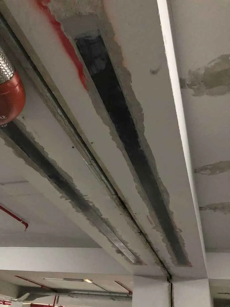
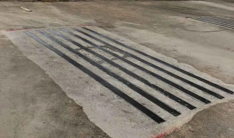
Figure 8: Application of FRP laminates in beams: (a) at midspan (lower side of the beam) and (b) at the supports (upper side of the beams)*
Figure 9: Application of FRP plates in slabs (a) at midspan and (b) at the supports*
In the case of columns, it is generally difficult to achieve the desirable upgrade in the critical regions with laminates, since this requires the lapping or anchorage of the plates inside the beam-column joint.
FRP laminates can also be used for the shear strengthening of beams with special L- or U-shaped systems. All the same, the lack of adaptability and versatility with respect to the FRP wraps renders them less appealing for this type of intervention. Laminates can be used in conjunction with FRP wraps for the simultaneous strength increase in bending (laminates) and shear (wraps) as in Figure 10.
Figure 10: Simultaneous strengthening of a beam in bending (with FRP laminates) and shear (with FRP wraps and FRP strips for anchorage)*
Contrary to the FRP wraps, the fibres in all FRP laminates are parallel to the plate axis. Similarly to the FRP wraps they can also be applied in more than one layers. It is noted however that the effectiveness of each new layer decreases with their number, because of the debonding between the first layer and the concrete surface and between the adjacent layers of the laminates [Mazzotti 2011]. As in the case with FRP wraps, the bond between the multiple layers and the concrete surface (which depends on the mechanical and physical properties of concrete, composite and adhesive) is a very important issue and bond failure is the most typical failure mode. Again, a minimum concrete tensile strength should be sought, so as to achieve good bonding conditions. When additional anchorage is needed, this is usually achieved by means of FRP strings, or special mechanical anchorage systems, usually steel or FRP composite plates placed at the edges of the laminate, in the perpendicular direction (Figure 11).

Figure 11: Mechanical anchorage of FRP laminates*
The application of FRP plates should always be done by a skilled and experienced crew. The preparation of the concrete surface is similar to the procedure followed for FRP wraps but generally it is done in a narrower area, due to the small width of the strips. After the substrate preparation (cleaning, removal of friable and grinding to level the surface), the laminate is thoroughly cleaned and a layer of the epoxy adhesive is applied with a spatula both on the laminate and the concrete to form a thin layer. Then the coated plate is placed onto the coated concrete surface and is pressed against it using a rubber roller, until the adhesive is forced out on both sides of the laminate. The surplus adhesive is then removed. When there are multiple layers or intersections, the upper strips are applied in the same way, however good cleaning of the lower (already placed) strips should be done beforehand. A thin layer of resin with quartz sand may be laid in order to improve the adhesion of the overlay, while measures for fire-resistance should be taken, if this is required by the design. Contrary to FRP wraps, the systems and the installation procedures of the different manufacturers are very similar, and all systems follow the procedure described above.
Figure 12: Application of FRP laminates*
NEAR SURFACE MOUNTED FRP REINFORCEMENT
An alternative to the external application of FRP laminates is the application of near surface mounted (NSM) FRP reinforcement. In this technique FRP plates are bonded in a groove cut in the concrete, rather than on the concrete surface [Parretti and Nanni 2004, El-Hacha and Rizkalla 2004]. Because the application should be done inside the concrete cover the plates are generally narrow with widths of 20mm, but have larger thicknesses of up to 3mm. After the installation of the plates, the groove is filled with an adhesive, which is usually an epoxy-based adhesive with filler, although in some cases of lower requirements, cement based adhesive may be employed.
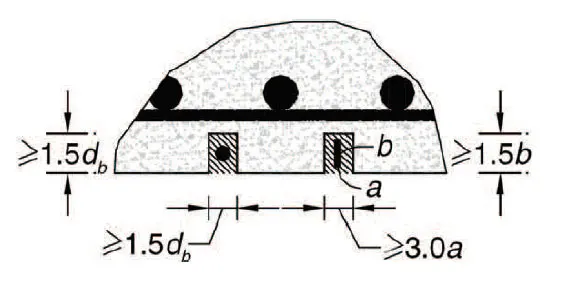
Figure 13: Near surface mounted (NSM) FRP reinforcement applied in the concrete cover [Szabó and Balázs 2007]*
Usually, NSM FRP reinforcement is used for flexural strengthening, providing increased strength and stiffness, but it can also be used for shear strengthening.
The main advantage of the technique is that it does not require extensive surface preparation (other than the grooving). Unlike the external FRP application, installation of the NSM system into cracked, rough or slightly damaged concrete is possible and independent of the surface tensile strength of the concrete. Furthermore, the procedure is generally faster and requires less installation time with respect to the externally bonded laminates. Because it has a larger bond surface, it provides better anchorage capacity and can mobilize a higher percentage of the tensile strength of the FRP plate. Finally, the system has improved protection against freezing, elevated temperatures and fire. Since the plates are embedded inside the concrete, they are better protected against accidental debonding and vandalism. Its most important disadvantage, which is probably the reason why NSM systems are not as common as their externally bonded counterpart, is the need for a relatively large cover depth (at least 2.5-3 cm), which is not so common in older, existing structures.
Before the application, the concrete cover depth needs to be checked, so as to make sure not to cut through existing reinforcing steel, embedded ducts, or more importantly steel tendons, or other materials within the substrate. The groove is cut using a diamond blade saw or agrinder, and is thoroughly cleaned from dust and lose parts. The groove is filled halfway with the adhesive, and the FRP plate is inserted and lightly pressed to let the adhesive flow around it. Finally, the groove is filled with more paste and the surface is levelled with a trowel. In order to improve adhesion with any possible additional layers, the adhesive may be covered lightly with quartz sand.
FRP STRINGS
These are unidirectional FRP strings, which are used as near surface reinforcement, and more often as fibre connector and anchorage of FRP wraps.
When installed as anchorage for the fabrics, they can be applied as (i) single connectors, whereby they are bonded into a prepared hole with an epoxy adhesive, and their outer half is usually placed into a star-shaped configuration and is attached to the FRP wrap edge, or as (ii) double connectors into a channel which goes through the concrete (for example through a beam), thus connecting the two edges of the FRP fabric – again the two edges of the FRP string are formed in a star-like shape (Figure 14). A very common application of the strings is to anchor the two edges of FRP wraps that are used for the shear strengthening of beams, where the slab does not allow for complete wrapping (Figure 15).
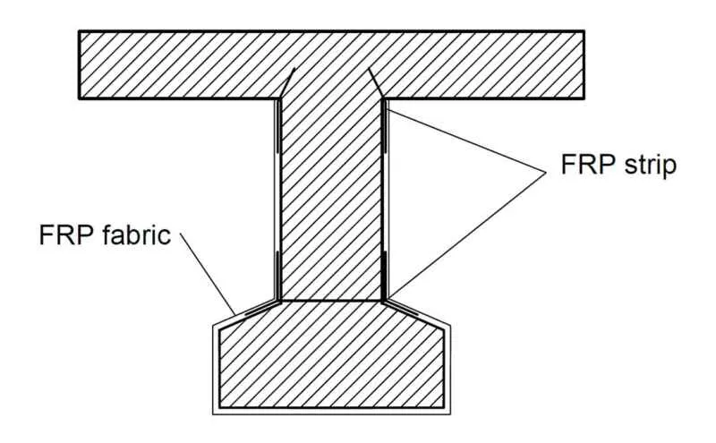
Figure 14: FRP strips as single and double connectors
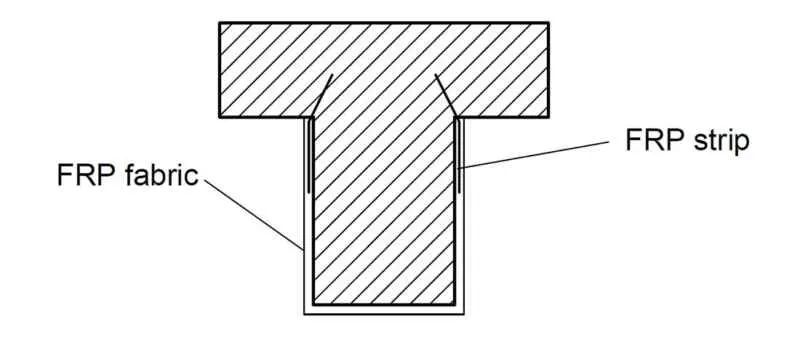
Figure 15: FRP strips used for the anchorage of FRP sheets for the shear strengthening of a beam
When used as mounted reinforcement, this is usually done at the supports region of beams or slabs, where an FRP laminate cannot be employed, for example because of the existence of columns or because it is the edge of the member and the laminate cannot be properly anchored. The strings are installed into small U-shaped slits that are opened in the concrete surface, which after the installation are filled with epoxy resin (Figure 16).


Figure 16: FRP strips used as additional support reinforcement of beams and slabs at their edges*
One important aspect in the application of FRP strings is that all the concrete edges should be rounded, when the string is applied at 90° angles, similarly to the case of FRP wraps. This is done in order to prevent the fracture of the fibres (and the consequent decrease of the effectiveness of the FRP system) when bent at right angles, and usually requires the opening of a round slit at the edge of the hole, where the string is anchored (Figure 17).

Figure 17: Strengthening in bending using FRP strips*
The preparation of the concrete substrate is similar to that for the NSM FRPs, and the cutting of the string into pieces is similar to that of the application of FRP wraps. Before installation the part of the strings that are to be anchored inside the concrete are impregnated until complete saturation, and tied with a plastic cable tie. The insertion inside the hole is done with a large spike or needle. Then the adhesive is applied to the prepared slits of the concrete surface with a brush, and the hole is filled with epoxy adhesive from the bottom up, in order to avoid air enclosures. In the case of systems for the anchorage of FRP fabrics, a dry remaining part of the string remains outside the slit. This is divided in equal parts or is opened as a tuft, and the fibres are impregnated with resin using a brush. The FRP fabric to be anchored is then installed.
SPRAYED-FRP
The set of FRP systems available on the market can be employed in a wide range of applications, nonetheless they also have significant drawbacks and limitations, such as the need for prior surface treatment, problems in the application of the method to strengthen beam-column joints, or in the upgrading of columns in bending. Currently under research are several new methods for the seismic strengthening of RC buildings, one of the most promising of which is the use of sprayed FRP. The method consists of the mixing of chopped glass and/or carbon fibres with epoxy and vinyl ester resin in open air and spraying the mix even onto surfaces, similarly to using shotcrete to cast concrete jackets.
The technique provides increased shear strengths and deformation capacities and can be used for the seismic strengthening of existing RC members. This can be achieved without the need for prior surface treatment, which is important, when the accessibility to the strengthened member is limited. The main disadvantages are that the method is still under research, it is not well tested, there are no guidelines available in the literature, and it requires special equipment that is not easily found on the market.
ANCHORING ISSUES
In closed wrapping the anchorage of the FRPs does not pose important design and construction challenges, and can be achieved with the overlapping of the FRP sheet in the fibre direction. On the contrary in open systems, such as FRP laminates, sided-boding or U-shaped wrapping, the debonding of the edge of the FRP fabric or plate is usually the critical failure mechanism, because of the low tensile strength of concrete. What is more debonding is a sudden and brittle type of failure. Hence ways to improve the bond between the FRP and the concrete surface and the stress transfer between them need to be found.
In some cases this can be easily achieved by extending the plate or sheet. This is usually done in the bending strengthening of beams and columns in the positive moments’ region at mid-span. The application of the FRP is done at the lower side of the member and can be extended towards the edges for better anchorage.
In other cases however this type of anchorage is not possible, for example in the strengthening of slabs and beams at the supports, where the extension of the plate or the sheet is obstructed by the presence of the overlying columns or because it is the edge of the member. In such cases, the use of an effective anchorage system is required. A large variety of anchorage systems are available and have been proposed in the literature [Grelle & Sneed 2013, Sneed 2013] and by FRP manufacturers. These serve the purpose of increasing the total available interfacial shear stress transfer, delaying interfacial crack opening and preventing the FRP debonding failure modes, and allowing more ductile and favourable failure mechanisms to develop.
Three main anchorage categories can be distinguished:
(i) Direct anchorage inside the existing concrete member. This is usually accomplished with FRP strings or spikes. The main idea behind it is to open a hole in the concrete of the existing member and anchor the FRP string (or FRP fabric + spike) inside it using a large quantity of epoxy adhesive. After the hole is filled with the resin, a piece of the FRP string or sheet remains outside the concrete substrate and is attached with more adhesive to the end of the load carrying FRP fabric or laminate (Figure 18a). Alternatively, two open edges of the FRP sheet can be closed with the application of the FRP string.
(ii) Increase of the ability to transfer the stresses by providing a clamping effect by means of transverse wrappingor FRP strings perpendicular to the axis of the laminate.
(iii) Increase of the ability to transfer the stresses by providing a clamping effect by means of mechanical anchorage systems, such as steel or anchor bolts, bolted steel plate anchors (Figure 18b), or bolted steel angles.
A very detailed review of the available anchoring options can be found in Grelle and Sneed [2013].

(a)

(b)
Figure 18: Different FRP anchorage systems*

Figure 19: Different FRP mechanical anchorage systems [Fukuyama et al. 2001]
ADVANTAGES AND DISADVANTAGES OF FRP SYSTEMS
The main characteristic of FRP materials is that they have a very high strength-to-weight ratio, thus allowing a significant strength increase of the reinforced concrete members without increasing the loads applied to the structure. Because they come in a variety of forms and systems, they can be tailored to meet wide-ranging performance specifications, flexural, confinement or shear only upgrade, or simultaneous flexural and shear upgrade. It is the only one, amongst the conventional strengthening techniques, that significantly increases the member strengths with only a minimal change in the overall structural stiffness distribution, hence it can be readily employed in selective intervention schemes.
The FRP layers that are added with the intervention are very thin (within the order of mm in the typical applications) and do not substantially alter the dimensions of the structural elements. This make the method more attractive than other jacketing methods, in cases when the dimensions of the existing member need to remain unaltered, e.g. columns adjacent to windows or doors that we do not want to change. Compared to other methods (new shear walls, RC jacketing with shotcrete) it is a very ‘clean’ method with minimal disturbance, and can be easily applied in buildings already in operation, without affecting the everyday life of the residents.
A key factor driving the increased applications of composites during recent years is the significant technological progress that has been achieved, allowing for new versatile FRP systems, new styles of reinforcement, high performance resins and most importantly the significant drop in their price. This, combined with the fast application and low labour installation costs, make them one of the most attractive strengthening solution.
Moreover, FRP materials possess excellent environmental resistance and durability and are often employed for anti-corrosion protection even in the most adverse environments, e.g. marine and coastal environments. They possess good impact, compression, fatigue and electrical properties, good thermal insulation, UV radiation stability and resistance to chemicals and corrosives.
On the negative side, one significant drawback of FRP materials is that they generally exhibit brittle behaviour with a linear elastic response up to failure. This applies to the failure mechanism under tension (i.e. fracture of the fibres), as well as to the more common failure modes, such as debonding.
FRPs exhibit poor resistance to fire and their capacity is seriously affected, because the resins quickly lose their strength in high temperatures. Hence, very often protective measures such as fire-resistant boards or mortars need to be applied. Furthermore, attention should be paid to protect FRP materials, particularly glass and aramid bars from the alkali environment in concrete, and aramid from UV radiation. All the same, protection from the alkali environment may be assured during the manufacturing stage by using proper coating materials. Finally, FRP composites are difficult to recycle, unlike other structural components such as steel.
DESIGN ISSUES
Figure 20 depicts the most common failure modes of reinforced concrete beams strengthened with FRP composites: (i) yielding of the steel in tension preceded or followed by rupture of the FRP sheet or plate under tension, (ii) compression failure of the concrete before yielding of the reinforcing steel and without FRP damage, (iii) failure of the concrete member in shear with diagonal cracking at the end of the plate, (iv) debonding of the FRP material, i.e. failure of the adhesive, (v) failure of the concrete cover and separation of the cover and the FRP composite from the rest of the beam, (vi) mid-span debonding initiated by flexural cracking and (vii) mid-span debonding initiated by flexural + shear cracks.
In most practical applications and for the typical configuration of existing members (e.g. relatively low concrete strength) the most crucial failure mode is the debonding of the FRP composite as controlled by the debonding stress. Therefore, the parameters that affect the bond and the transfer of stresses between the FRP laminate and the concrete member, such as the mechanical characteristics of the epoxy adhesive, the strength of the existing concrete and the correct surface preparation of the substrate, all assume a very important role in the final capacity of the strengthened member. If adequate anchorage conditions cannot be guaranteed, additional anchoring systems should be introduced, especially in the cases when complete wrapping is not possible, due to geometrical or accessibility conditions.
Fire should also be included as a limit state as it will influence the properties of both the FRP and the adhesive used to attach it to the concrete.

Figure 20: Types of failure in FRP strengthened concrete members [Danraka et al. 2017]
Most modern Standards for structural rehabilitation provide guidelines for the design of strengthening of RC members with FRP systems in shear, flexure and confinement. The design procedure is usually based on the following assumptions: there is no slip between the FRP and the concrete, the shear deformation within the adhesive layer is neglected, the tensile strength of concrete is negligible and the FRP laminate has a linear elastic stress-strain relationship up to a brittle failure.
One important aspect of the interventions with FRP composites is that their effect in the structural stiffness distribution is negligible. Hence, it is the only method, whereby the strengthening can be directly calculated based on the member demand as given from the analysis of the existing building, without the need to rerun the entire analytical procedure to make sure there is no significant increase in the member demand, as a result of the structural intervention.
Nowadays, most of the national Standards for retrofit and upgrading include relatively large sections about strengthening with FRP composites. Moreover, there are several documents that provide complete guidelines and cover the subject in more detail. Amongst them, the American ACI 440 document [ACI 2017] is probably the most comprehensive, influential and widely used. Other notable guidelines are the fib-TG9.3 technical report 14 in Europe [FIB 2001], the Italian guidelines CNR-DT 200 R1/2013 [CNR-DT 200 2013], the CAN/CSA-S806-02 Canadian Guidelines [Canadian Standards Association 2007], the Japan Society of Civil Engineers recommendations [JSCE 2001] and Technical Report 55 from the British Concrete Society [The Concrete Society 2004].
References
- [ACI] American Concrete Institute ACI 440, 2017: ACI PRC-440.2-17: Guide for the Design and Construction of Externally Bonded FRP Systems for Strengthening Concrete Structures. ACI Committee 440.
- Belarbi A. and Acun B. 2013. FRP Systems in Shear Strengthening of Reinforced Concrete Structures. 11th International Conference on Modern Building Materials, Structures and Techniques,MBMST 2013. Procedia Engineering 57 (2013) 2 – 8. Available at: https://doi.org/10.1016/j.proeng.2013.04.004.
- Canadian Standards Association, 2007. CAN/CSA-S806-02 (R2007). Design and Construction of Building Components with Fibre-Reinforced Polymers.
- CNR-DT 200 (2013), Istruzioni per la Progettazione, l’Esecuzione ed il Controllo di Interventi di Consolidamento Statico mediante l’utilizzo di Compositi Fibrorinforzati, Centro Nazionale Ricerche, Commissione di Studio per la Predisposizione e l’Analisi di Norme Tecniche relative alle costruzioni, Roma.
- Danraka M.N., MahmodH.M., OluwatosinO.-k.J., 2017. Strengthening of reinforcedconcrete beams using FRP technique: a Review.International Journal of Engineering Science 7 (6) (2017) 13199.
- El-Hacha R. and Rizkalla S., 2004. Near-Surface-Mounted Fiber-ReinforcedPolymer Reinforcements for Flexural Strengthening of Concrete Structures”, ACIStructures Journal, Vol. 101, No. 5, September-October 2004, pp. 717-726.
- [FIB] Fédération Internacionale du béton (2001). Externally bonded FRP reinforcement for RC structures. Fib bulletin 14 Technical Report. International Federation of Structural Concrete, Lausanne. Task Group Fib TG9.
- Fukuyama, H, Tumialan, G. and Nanni, A, 2001. Japanese Design and Construction Guidelines for Seismic Retrofit of Building Structures with FRP Composites. Proceedings of the International Conference on FRP composites in Civil Engineering. Hong Kong, China. December 2001.
- Grelle, S.V. and Sneed, L.H 2013. Review of Anchorage Systems for Externally Bonded FRP Laminates. Int J Concr Struct Mater 7, 17–33 (2013). Int J Concr Struct Mater 7, 17–33 (2013). Available at: https://doi.org/10.1007/s40069-013-0029-0
- Gudonis E., Timinskas E., Gribniak V., Kaklauskas G., Arnautov A.K. and Tamulėnas V. 2013. FRP reinforcement for concrete structures: state-of-the-art review of application and design. Engineering Structures and Technologies Volume 5, 2013 – Issue 4, pg. 147-158. Available at: https://doi.org/10.3846/2029882X.2014.889274
- [JSCE] Japan Society of Civil Engineering Recommendations, 2001. Recommendations for Upgrading of Concrete Structures with Use of Continuous Fiber Sheets. JSCE, Concrete Engineering Series 41. Edited by Kyuichi Maruyama.
- Karataş M.A., Gökkaya H . 2018. A review on machinability of carbon fiber reinforced polymer (CFRP) and glass fiber reinforced polymer (GFRP) composite materials. Defence Technology, 14 (2018) 318-326– Elsevier.
- Masuelli M.A., 2013, Introduction of Fibre-Reinforced Polymers − Polymers and Composites: Concepts, Properties and Processes, http://dx.doi.org/10.5772/54629
- Mazzotti C., 2011. The effect of the number of strengthening layers on the FRP-concrete bond behaviour. European Journal of Environmental and Civil Engineering 15(9):1277-1296. November 2011. DOI: 10.1080/19648189.2011.9714855
- Parretti R. and Nanni A. 2004. Strengthening of RC Members Using Near-SurfaceMounted FRP Composites: Design Overview. Advances in Structural Engineering Vol. 7 No. 5 2004.
- Sneed L. H., 2013. Review of Anchorage Systems for Externally Bonded FRP Laminates, March 2013. DOI: 10.1007/s40069-013-0029-0.
- Szabó K.Z. and Balázs L.G. 2007. Near surface mounted FRP reinforcementfor strengthening of concrete structures, Periodica Polytechnica 51 (2007),no. 1, 33–38, DOI 10.3311/pp.ci.2007-1.05.
- The Concrete Society 2004: Design guidance for strengthening concrete structures using fibre composite materials. The UK Concrete Society. Technical Report No. 55, 2nd ed. – ISBN 1904448247.
- Triantafyllou A., 2004. Strengthening of Reinforced Concrete Structures with Composite Materials (Fibre-Reinforced Polymers). Patras 2004. In Greek.
- *All the pictures, which are in the article and are not referenced, are courtesy of Alfakat (www.alfakat.gr), an official partner of Seismosoft.
- Structural Assessment, Strengthening & Retrofitting carried out using SeismoSoft Earthquake Engineering Software.